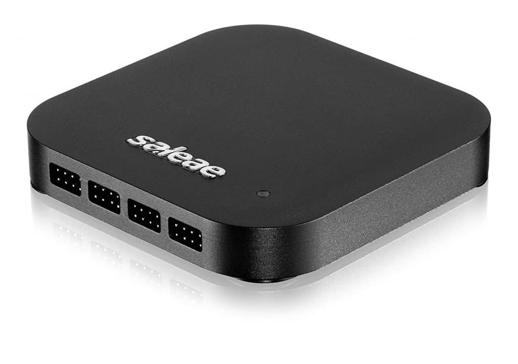
| Channels | Sixteen digital inputs, sixteen analog inputs (shared with digital channels) |
| Maximum Sample Rates | Digital: 500 MSPS @ 4 channels, 100 MSPS @ 16 channels (USB 3.0 required)
Analog: 50 MSPS @ 3 channels, 12.5 MSPS @ 13 channels, 6.25 MSPS @ 16 channel |
| Bandwidth | Digital: 100 MHz square wave when sampling at 500 MSPS Analog: 5 MHz when sampling at 50 MSPS |
| Trigger | Edge or pulse width trigger |
| Supported Protocols | Serial, SPI, I2C, Atmel SWI, Biss-C, CAN, DMX-512, HD44780, HDLC, I2S, JTAG, LIN, MDIO, MIDI, Manchester, Modbus, 1-Wire, PS/2 Keyboard & Mouse, SMBus, SWD, Synchronous Parallel, USB, UNI/O, CUSTOM |
| Capture Buffer Length | Limited by installed memory and digital data density. When recording analog at 50 MSPS, captures 10-60 seconds usually possible. Without analog, buffer length is dependent on digital activity density. 1 MHz SPI: up to 10 Minutes. I2C – several hours – 9600 baud serial – over 1 day. |
| Analog Resolution | 12 bits, 4.88 mV per LSB |
| Analog Input Range | -10V to 10V |
| Supported digital IO standards | 1.2V, 1.8V, 2.5V, 3.3V, 5.0V, RS-232, +12V TTL |
 Overview
 Customers
 Technology
 Management
 News & Event


